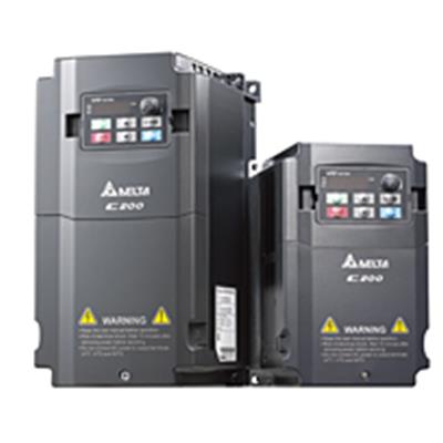
Introduction to control mode of Delta inverter
Today, Shanghai Kuanying Automation Equipment Co., Ltd. takes you to understand Delta’s frequency conversion Several control methods of the device:
The low-voltage universal variable frequency output voltage is 380-650V, the output power is 0.75-400kW, the working frequency is 0-400Hz, and its main circuit adopts the AC-DC-AC circuit. . The way it is controlled has gone through the following four generations. 1U/f=C sinusoidal pulse width modulation (SPWM) control mode: It is characterized by simple control circuit structure, low cost, good mechanical properties and hardness, which can meet the requirements of smooth speed regulation of general transmission, and has been used in various industries. The field is widely used. However, in this mode of control, at low frequencies, the torque is affected by the voltage drop of the stator resistance due to the lower output voltage, which reduces the output torque. In addition, its mechanical characteristics do not have DC motor hard, dynamic torque capability and static speed regulation performance are not satisfactory, and the system performance is not high, the control curve will change with the load change, the torque response is slow, the motor turns The moment utilization rate is not high, and the performance is degraded due to the existence of the stator resistance and the dead zone effect of the inverter at a low speed, and the stability is deteriorated. Therefore, people have also studied vector control frequency control.
Voltage Space Vector (SVPWM) Control Method:
It is based on the overall effect of three-phase waveform generation, aiming at the ideal circular rotating magnetic field trajectory approaching the motor air gap. A three-phase modulation waveform is generated at a time, and is controlled by an inscribed polygon approaching a circle. After practice, it has been improved, that is, the introduction of frequency compensation can eliminate the error of speed control; estimate the magnitude of the flux linkage through feedback to eliminate the influence of stator resistance at low speed; close the output voltage and current to improve the dynamic accuracy and stability. However, there are many control circuit links and no torque adjustment is introduced, so the system performance has not been fundamentally improved.矢
Quantity Control (VC) Mode:
Vector Control Variable Frequency Speed Regulation is to use the asynchronous current in the three-phase coordinate system of stator currents Ia, Ib, Ic, through three The phase-to-two-phase transformation is equivalent to the alternating current Ia1Ib1 in the two-phase stationary coordinate system, and then transformed into the DC current Im1 and It1 in the synchronous rotating coordinate system by the rotational transformation of the rotor field. (Im1 is equivalent to the DC motor. Excitation current; It1 is equivalent to the armature current proportional to the torque), and then simulates the control method of the DC motor to obtain the control amount of the DC motor, and realizes the control of the asynchronous motor through the inverse inverse transformation of the corresponding coordinates. The essence is that the AC motor is equivalent to a DC motor, and the two components of speed and magnetic field are independently controlled. By controlling the rotor flux linkage and then decomposing the stator current, two components of torque and magnetic field are obtained, and coordinate transformation is performed to realize orthogonal or decoupling control. The proposed vector control method has epoch-making significance. However, in practical applications, because the rotor flux linkage is difficult to accurately observe, the system characteristics are greatly affected by the motor parameters, and the vector rotation transformation used in the equivalent DC motor control process is complicated, making the actual control effect difficult to achieve the ideal analysis. result.
Direct Torque Control (DTC):
In 1985, Professor DePenbrock of Ruhr University in Germany proposed direct torque control frequency conversion technology. This technology largely solves the above-mentioned shortcomings of vector control, and has been rapidly developed with novel control ideas, simple and clear system structure, and excellent dynamic and static performance. At present, this technology has been successfully applied to high-power AC drives for electric locomotive traction. The direct torque control directly analyzes the mathematical model of the AC motor in the stator coordinate system to control the flux linkage and torque of the motor. It does not require the AC motor to be equivalent to a DC motor, thus eliminating many of the complex calculations in vector rotation transformation; it does not require the control of a DC motor, nor does it need to simplify the mathematical model of the AC motor for decoupling.


