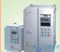
Emerson inverter drive circuit common problems and solutions
In Emerson Inverter The ever-expanding nature of inverter drive circuit technology is changing with each passing day. The drive circuit is just a general term, and it itself has gone through the drive circuit from the pin type component to the optocoupler drive circuit, to the thick film drive circuit, and the new integrated drive circuit. The driver circuit plays a vital role in the quality of an Emerson inverter. 1. Causes of damage to the drive circuit and inspections The causes of drive damage are various. In general, the problems that occur are nothing more than U, V, W three-phase output or output. Unbalanced, or output balance but jitter at low frequencies, as well as start alarms. When the fast fuse after a large capacitor of the inverter is disconnected, or the IGBT inverter module is damaged, the drive circuit is basically impossible to be intact, and it is not necessary to replace it with a good fast fuse or IGBT inverter module. This can easily cause the new device that has just been replaced to be damaged again. At this time, it should be checked whether there is a flashing mark on the driving circuit. The driving pin connection of the IGBT inverter module can be unplugged first, and the resistance of the six-way driving is measured by the multimeter electric blocking (but very few The inverter drive circuit is not the same as the six-way resistance, such as Mitsubishi, Fuji and other inverters. If the six-way resistance is basically the same, it is not completely proved that the driving circuit is intact. Then, an electronic oscilloscope is needed to measure whether the voltages on the six-way driving circuit are the same. When the waveform of the six-way driving circuit is the same when a starting signal is given, if there is no electronic oscilloscope, it is also possible to use a digital electronic multimeter to measure the DC voltage of the driving circuit six. Generally speaking, the DC voltage on each driving circuit when starting is about 10V, and the DC voltage after starting is 2-3V. If the measurement result is normal, it can be basically judged that the driving circuit of the inverter is good. Then connect the IGBT inverter module to the drive circuit, but remember that in the absence of 100% confidence, the safe method is to disconnect the P of the IGBT inverter module from the DC bus. A group of bulbs or a resistor with a higher power, so that the IGBT inverter module can be prevented from being burnt out by the discharge current of the large capacitor in the case of a large current in the circuit. 2. Inverter drive circuit maintenance example <1> (1) Fuji G9 inverter
The phenomenon of failure is power-on and no display. It is estimated that the inverter switching power supply is damaged. Turn on the inverter to check the switching power supply line. However, after checking, the switching power supply device circuit is not damaged, and the DC voltage is not displayed. At this time, it may be estimated that it may be a driving problem. Remove all the capacitors of the drive circuit and find that some capacitors leak liquid, replace the new electrolytic capacitors, and work normally after power-on again. (2) Delta inverter
The fault phenomenon is that the output of the inverter is ignited. After the disassembly and inspection, it is found that the IGBT inverter module breaks down and the printed circuit board of the drive circuit is seriously damaged. The correct solution is to first remove the damaged IGBT inverter module. When disassembling, the printed circuit board should be protected from secondary damage as much as possible. The damaged electronic components on the driving circuit are replaced one by one, and the open circuit of the printed circuit board is connected by wires (it is necessary to scrape the burned parts to prevent re-ignition). Use the oscilloscope to measure the waveform when the resistance of the six-way drive circuit is the same and the voltage is the same, but the OCC fault is reported when the inverter is turned on (the Delta inverter has no IGBT inverter module, open the opportunity alarm). Use the bulb to P1 and print the module. The boards are connected. Other wires are connected, and the OCC is reported again, and it is determined that there is a problem with the driving circuit; the optical coupler is replaced one by one, and the optical coupler with the detecting function of the driving circuit is detected, and one of the optical couplers is detected. Damaged, after a new one, the start is normal.


