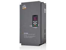
Shilin Inverter manufacturers teach you how to distinguish the quality of the inverter IGBT
There are certain uses in many professions. When the inverter is in use, we need to know about the general knowledge of the inverter. In the meantime, the quality of the IGBT of the inverter is very important for the inverter, which is related to whether the inverter can be used normally. Shilin Inverter manufacturers teach you how to distinguish the quality of the inverter IGBT
1. Thyristor polarity and good or bad methods
Select the pointer multimeter R × 100Ω or R × 1KΩ file to measure the positive and negative resistance between the two poles of the thyristor, one pole and the other north and south If the forward and reverse resistances are both infinite, then the extreme anode (A) is determined. Then pick the R x 1 Ω file of the pointer multimeter. The black meter is connected to the anode (A) of the thyristor, and the red pole is connected to the thyristor with one pole being assumed to be the cathode (K) and the other pole being the gate (G). Do not leave the anode (A) and touch the steering pole (G). If the pointer of the multimeter is deflected and stood, it is determined that the assumed polarity cathode (K) and the steering pole (G) of the thyristor are correct, and the thyristor component is Good thyristor. If the multimeter pointer is not deflected, reverse the assumed polarity of the thyristor and measure it. If the multimeter pointer deflects and stands, the second assumed polarity of the thyristor is correct and the thyristor is a good thyristor. Otherwise it is a bad thyristor.
2. Method for judging IGBT polarity and good or bad
Discriminating IGBT polarity: Selecting a pointer multimeter R×100Ω or R×1KΩ to measure any two poles of the IGBT The positive and negative resistance between the one pole and the other north and south poles are infinite, and the gate (G) of the extreme IGBT is determined. Measure the forward and reverse resistance of the other north and south poles. In the forward resistance, the red meter is connected to the collector (C) of the IGBT, and the black meter is connected to the emitter of the IGBT (E)
Good or bad: Pick the R×10KΩ file of the pointer multimeter. The black pen is connected to the collector (C), the red pen is connected to the emitter (E), and the collector (C) and the control electrode (G) are touched by hand. If the multimeter pointer deflects and stands, and then touches the emitter (E) and the steering pole (G) together by hand, the multimeter pointer returns to zero, then the IGBT is good, otherwise it is a bad IGBT.
The quality module's discrimination is mainly based on the identification of the freewheeling north and south poles in the power module. For the IGBT module, we need to determine whether it can be turned on and off in the presence of a trigger voltage.
3. Inverter inverter IGBT module detection:
Dial the digital multimeter to the diode test file and test the IGBT module c1 e1, c2 e2 and gate G and e1 , the forward and reverse diode characteristics between e2 to determine whether the IGBT module is intact.
Take the six-phase module as an example. Remove the wires of the U, V, and W phases on the load side, use the diode test file, connect the red meter pen to P (collector c1), and the black test pen sequentially measures U, V, W. The multimeter shows the value as zui; the test pen is reversed. The black pen is connected to the P, the red pen is measured U, V, W, and the multimeter has a value of about 400. Then connect the red test pen to N (emitter e2), the black test pen to measure U, V, W, the multimeter shows the value of about 400; the black test pen is connected to P, the red test pen is measured U, V, W, and the multimeter shows the value as zui. The forward and reverse characteristics of each phase should be the same. If the difference indicates that the function of the IGBT module is deteriorated, it should be replaced. When the IGBT module is damaged, only the breakdown short circuit is presented.
The red and black pens are separated from the positive and negative characteristics between the gate G and the emitter E. The values measured by the multimeter twice are large, and the IGBT module gate is normal. . If a value appears, the gate function deteriorates and the module should be replaced. When the forward and reverse test results are zero, it indicates that the detected one-phase gate has been broken through. When the gate is damaged, the voltage regulator of the board maintenance gate will also be damaged by breakdown.


