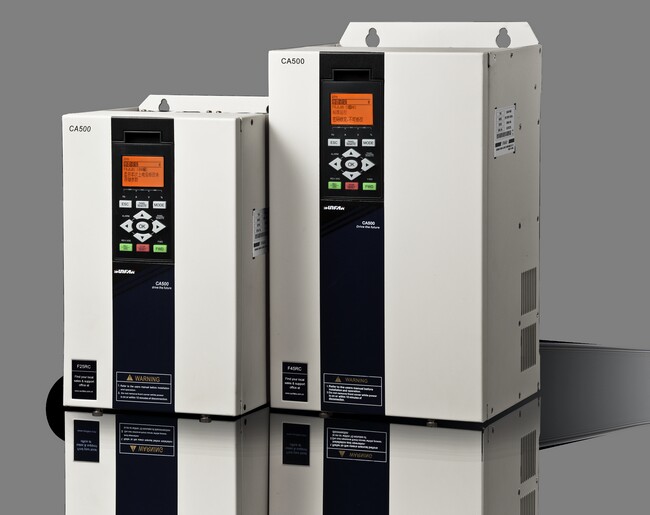
What is Huichuan Inverter and how to do inverter wiring
How the frequency converter works
The main circuit is a power conversion part that supplies a voltage-regulating and frequency-modulated power supply to an asynchronous motor. The main circuit of the Huichuan frequency converter can be roughly divided into two types: the voltage type converts the direct current of the voltage source into an alternating current. Inverter, DC circuit filtering is a capacitor. The current type is a frequency converter that converts the direct current of the current source into an alternating current, and the direct current loop filtering is an inductance. It consists of three parts, which converts the power frequency power supply into a "rectifier" of DC power, absorbs the "flat wave loop" of the voltage ripple generated by the converter and the inverter, and converts the DC power into the "reverse" of the AC power. Transformer."
1. Main circuit wiring
1. The power supply should be connected to the inverter input terminals R, S, T wiring. The terminal must not be connected to the inverter output (U, V, W), otherwise the inverter will be damaged. After wiring, the broken wire ends must be cleaned, and the broken wire ends may cause abnormalities, malfunctions and malfunctions, and the frequency converter must always be kept clean. When punching holes in the console, be careful not to let debris powder enter the inverter.
2, between the terminals +, PR, do not connect anything other than the recommended brake resistor option, or do not short circuit.
3. Electromagnetic interference, the input/output (main circuit) of the inverter contains harmonic components, which may interfere with the communication equipment near the inverter. Therefore, install the optional radio noise filter FR-BIF or FRBSF01 or FR-BLF line noise filter to reduce the interference.
4. In the long-distance wiring, due to the influence of the parasitic capacitance charging current of the wiring, the fast response current limiting function is lowered, and the instrument connected to the secondary side malfunctions to cause a malfunction. Therefore, the length of the routable wiring is smaller than the specified value. When the length of the wiring must be exceeded, it is necessary to put Pr. 156 is set to 1.
5, Do not install power capacitors, surge suppressors and radio noise filters on the output side of the inverter. Failure to do so may result in damage to the drive or damage to the capacitor and surge suppressor.
6, in order to make the voltage drop within 2%, should use the appropriate type of wire wiring. When the wiring distance between the inverter and the motor is long, especially in the case of low frequency output, the torque of the motor will drop due to the voltage drop of the main circuit cable.
7. After the operation, the operation of changing the wiring must be performed after the power supply is cut off for 10 minutes or more, and the voltage is checked with a multimeter. There is still a dangerous high voltage on the capacitor for some time after the power is turned off.
Second, the wiring of the control circuit
The control circuit of the inverter can be roughly divided into analog and digital.
1. The wiring of the control circuit terminals should be shielded or twisted, and must be routed separately from the main circuit and the high-voltage circuit (including the 200V relay program circuit).
2. Since the frequency input signal of the control circuit is a small current, in the case of contact input, in order to prevent contact failure, the small signal contact should use two parallel nodes or use twin contacts.
3. The wiring of the control circuit is generally selected from 0.3 to 0.75 square meters.
3. Ground wire connection
1. Since there is leakage current in the inverter, in order to prevent electric shock, the inverter and motor must be grounded.
2. Dedicated grounding terminal for inverter grounding. For the connection of the grounding wire, use tinned crimp terminals. When tightening the screws, be careful not to damage the turnbuckle.
3. Lead is not contained in tin plating.
4, the grounding cable should be as thick as possible, must be equal to or greater than the specified standard, the grounding point should be as close as possible to the inverter, the shorter the grounding wire, the better.
1, the inverter itself has strong electromagnetic interference, it will interfere with the work of some equipment, so we can add on the output cable of the inverter Upper cable sleeve.
2, the control line in the inverter or control cabinet is at least 100mm from the power cable, and so on.
3, there will be a description of the inverter when purchasing the inverter. If not, you can download it from the website of the brand you purchased. The above contents of the inverter manual are quite detailed, including product introduction, working principle, installation and debugging, and so on.


